
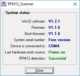
RFM12_Scanner
 DIY ISM band RF scanner with RFM12 transceiver module
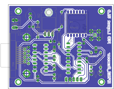
PCB-Layout: V1.0
PC-Software: V1.2.1
Manual: V1.0.2
Firmware: V1.1.6
German manual: Download
English manual: Download
Firmware: Download
Eagle PCB: Download
Did you ever wonder, how a RFM12 module "sees" its RF-environment ?
Are you looking for an unoccupied frequency ?
Here is a solution that makes an expensive spectrum-analyzer for simple (and even not so simple) tests obsolete !
The "What's new ?" section has been moved to a new page : View
General
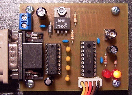
- You need 1 RFM12 module, 1 PIC16F88 (†) programmed with the latest RFM12_Scanner firmware, 1 RS232 level-shifter (e.g.MAX232N), some passive components and a
"clean" power supply within the range from 8V to 20V.
Double the amount of parts for a TX-/RX-combination that can be used to test the properties of a certain radio link topology. Though there is no convenient interface to the firmware's transmitter routines at the present time (this is one of the next "ToDos"), the initial transmitter-routine can be used "the hard way" with a terminal software capable of sending, receiving and displaying hexadecimal values directly.
Use the communication-parameters and -protocol described in section "Communicating using a terminal software" on this page and see section "Transmitter" to learn more about the TX-mode available at the present time.
(†) A PIC16F87 should work as well, but this was not tested ! - The display can be saved as a bitmap or it can be loaded and saved as RFM12_Scanner data files.
- By default the 433MHz band is selected - the 315MHz-, 868MHz- and 915MHz-band RFM12-versions are fully supported as well.
- The chosen frequency range must be supported by your module's hardware.
- Reconfiguration of the module's hardware to the band-selection in the pc-software happens automatically.
- The LNA gain is selectable.
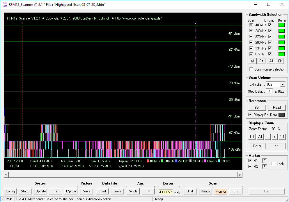
- All six RFM12-receiver bandwidths can be scanned apparently simultaneously in a single pass.
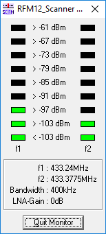
- A single frequency monitor allows display of the received fieldstrength in a LED-meter style.
- COM1: to COM16: are supported, "Virtual Com Ports" included (e.g. USB to serial converters).
- Two graphical markers allow to limit a scan action to a frequency range in the chosen band and to mark frequencies of interest.
- A scan action can be repeated continuously by selecting the "Scan/Monitor" option. During a "Scan/Monitor"-action, the display is not cleared between the single scans to preserve the information displayed.
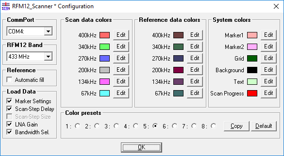
- The colors used in the graphical display can be defined freely and saved to or loaded from up to eight different color-sets (presets).
- The displayed data can be copied to a "Reference"-buffer to be displayed additionally during a scan-action.
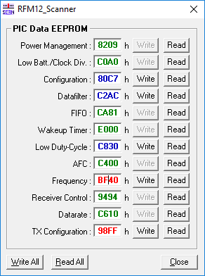
- The pc-software includes an editor for the RFM12-configuration values stored in the microcontroller's internal data EEPROM.
- Bandwidths for the next scan action and bandwidths to display can be selected independently.
This piece of software was developed using the information provided in the RF12 datasheet.
No other RF-measurements than with the device described on this page were made to verify these
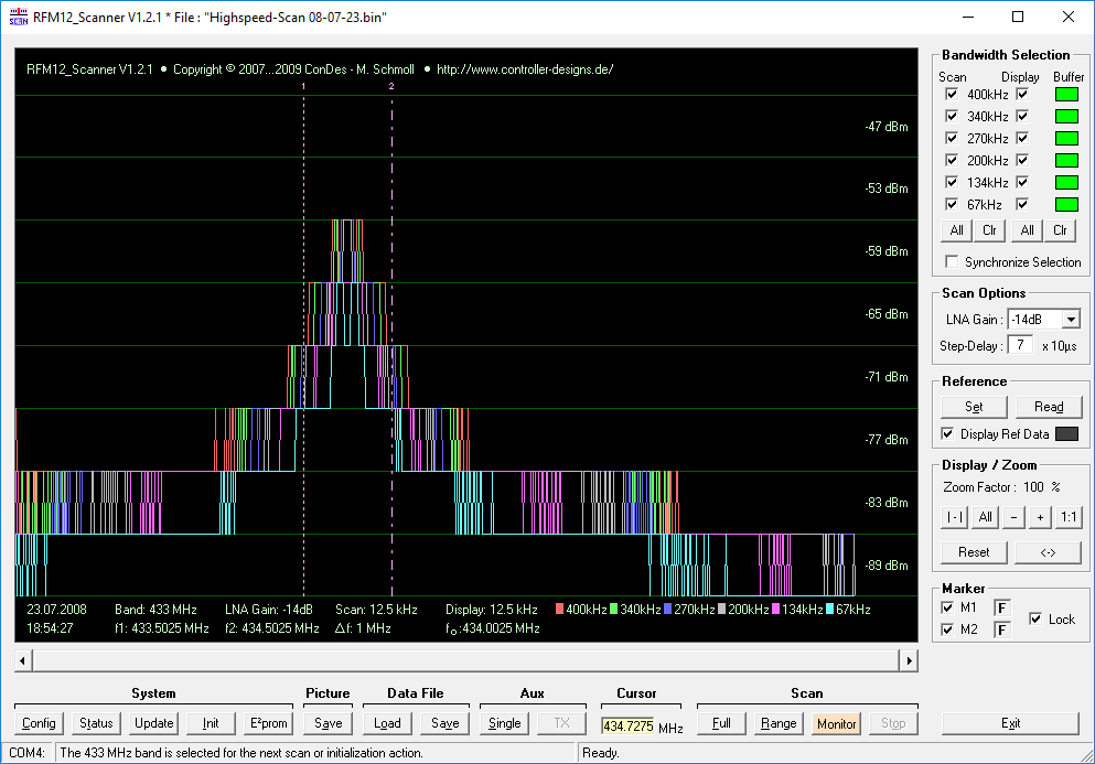
(It is possible to read out a center frequency of 434.0025MHz, if the transmitter is tuned to 434MHz - at the default scan step-size of
5 * fres (= 5 * 2,5kHz = 12,5kHz for a 433MHz band module)).
Scan ranges for different RFM12 types
| RFM12 | f(start) [MHz] | f(end) [MHz] |
|---|---|---|
| 315MHz | 310.24 | 319.7525 |
| 433MHz | 430.24 | 439.7525 |
| 868MHz | 860.48 | 879.505 |
| 915MHz | 900.72 | 929.2575 |
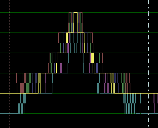
Screenshots (resized)
Click here to view full size screenshots.
Important signal connections
Supply connections etc. excluded !
| Signal - RFM12 | Signal - PIC16F88 | Signal - MAX232 (†) | Aux |
|---|---|---|---|
| FSK/DATA/nFFS | - | - | Pullup 10k to Vdd |
| nSEL | PORTA,0x01 | - | - |
| SCK | PORTA,0x02 | - | - |
| DI | PORTA,0x03 | - | - |
| DO | PORTA,0x04 | - | - |
| - | PORTB,0x02 | Receiver Out | - |
| - | PORTB,0x05 | Transmitter In | - |
| - | PORTA,0x06 | - | B1 (series resistor (‡) !) |
| - | PORTA,0x07 | - | B2 (series resistor (‡) !) |
(†) Connect all unused level-shifter TTL-inputs to GND or +5V.
(‡) The correct value for the LED's series resistors depends, of course, on what type of LEDs you are using.
RFM12_Scanner schematic
There is no need (and no connection) for a crystal at the PIC16F88 in this configuration, because it runs with its internal RC oscillator.
Communicating using a terminal software
The microcontroller software provides a rudimentary user interface using the microcontroller's asynchronous serial interface. It is recommended to use the "ConDes RS232 Tester" software (free download from this site) for sending and receiving data to and from the RFM12_Scanner, because you will have to enter and display data directly as hexadecimal values.
Interface parameters : 38400 bps / 8 databits / No parity / 1 stopbit
Reading and writing the RFM12 initialization values
The microcontroller's internal EEPROM is used to store the initialization values for the RFM12 module, which are loaded automatically on each reset (e.g. power on, external reset). This allows easy reconfiguration of the module, e.g. to another transmitter configuration, TX frequency, datarate etc. As mentioned above, you will have to reset the device to load the changed configuration values into the RFM12.
Starting with pc-software V1.1.7, there is no need to reprogram the microcontroller's data EEPROM to configure the RFM12 to a band other than the default 433MHz-band !
Starting with V1.1.9, the pc-software includes an editor for the RFM12 configuration values stored in the microcontroller's internal EEPROM, what makes editing the EEPROM and communicating with the RFM12_Scanner device "the hard way" obsolete !
Valid command codes for EEPROM access and the protocol are :
|
Read internal EEPROM (RFM12 Config) PC uC 0x04 -> (†) <- 0x04 Address-> <- Data =============================================== Write internal EEPROM (RFM12 Config) PC uC 0x05 -> <- 0x05 Address-> Data -> <- Data (Read back from EEPROM) |
(†) What is meant here, as in all protocol descriptions on this page, if not marked differently, is a single byte with the value 0x04 - not a sequence of bytes, consisting of the ASCII-codes for each character in "0x04".
Here is the memory map (Address 00 = HighByte, address 01 = LowByte...) :
|
00,01 Power Management 02,03 Low Batt / Clock Divider 04,05 Configuration 06,07 Datafilter 08,09 FIFO 0A,0B Wakeup Timer 0C,0D Low Duty-Cycle 0E,0F AFC 10,11 Frequency 12,13 Receiver Control 14,15 Datarate 16,17 TX Configuration ... 20 TX test-value (1 Byte) |
It is suggested to use the "ConDes RFM12_Eva Command Code Generator" (free download available) to conveniently encode and decode the RFM12 configuration-values.
Transmitter
The RFM12_Scanner device can be used as a test-transmitter, for example to test the properties of a certain radio link topology with two RFM12_Scanner devices, even as long as there is
no convenient user interface and the enhanced TX-test routines are not activated.
After receiving the correct command-code from the serial interface, the TX-block of the RFM12 is switched on and the RFM12_Scanner firmware continuously sends the value specified at EEPROM address 0x20 (0xAA by default)
to the antenna using FSK modulation until one byte is received by the RS232-interface.
This transmit-mode is entered by sending "07" (†) to the microcontroller. The microcontroller responds with "07", the transmitter is switched on
and both LEDs are switched off. It is recommended to use the value "00" to switch the transmitter off, because this command code does not interfere with any other part
of the software ("00" is the command code for reading the device-ID and primary (‡) software version from the microcontroller. The µC responds
with "00" followed by the deviceID (0F for RFM12_Scanner), value for firmware version major, firmware version minor and firmware version revision (e.g. 00 0F 01 01 05 for firmware version >=1.1.5)).
(†) What is meant here, as in all protocol descriptions on this page, if not marked differently, is a single byte with the value 0x07 - not a sequence of bytes, consisting of the ASCII-codes for each character in "0x07".
(‡) Starting with firmware version 1.1.5, there is an extended set of commands.
This piece of software was developed using the information provided in the RF12 datasheet.
No other RF-measurements than with the device described on this page were made to verify these.
Visit this page from time to time to check for updates.
Bookmark this page